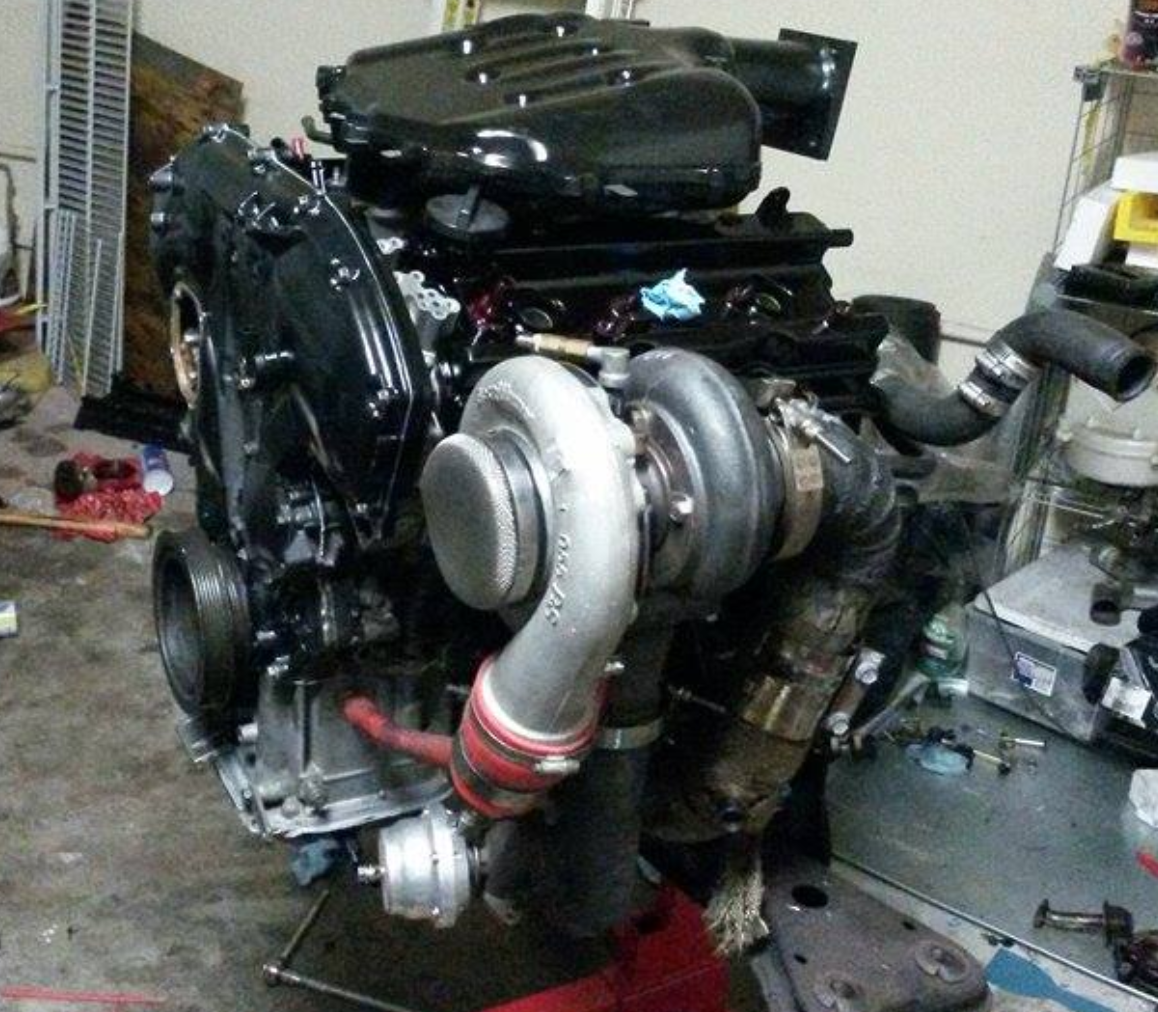
Posted on 2 Comments

What is Engine Tuning?

This is a topic that a lot of people tend to avoid. They find it difficult before sitting down and trying it or looking it up; its treated like math in a way. I’d like to give an overview of what engine tuning is in layman terms. I will go over an engines mechanics, fuel, timing, sensors and tuning devices.

Engine Basics

An engine is a block of metal that has holes(cylinders) 95.5mm in diameter in the case of a VQ35. Below the cylinders inside the block there is a separate rotating piece of metal called a crank. Inside a cylinder there is a piston that moves up and down, pressurizing as they go up since the top of the cylinder is blocked off by whats called a head. Air and fuel is sent into the cylinder through the head and a spark plug that is screwed through the head and into the cylinder ignites the mixture.

This explosion pushes the piston down into a rod that’s connected to the rotating crank. The stronger the explosions within the cylinders the more force there is to rotate the crank. The crank is connected to the transmission which then sends the torque to the wheels and moves the car.

4-Stroke-Engine-with-airflows
4-Stroke-Engine.gif: UtzOnBike (3D-model & animation: Autodesk Inventor)derivative work: Cuddlyable3 at en.wikipedia [GFDL or CC-BY-SA-3.0], via Wikimedia Commons

Fuel and Timing

The fuel entering the combustion is controlled by the injectors spray. The rate in which the injectors open and close and the duration while open determines the amount of fuel delivered. The injectors are controlled by the cars computer, the ECU(engine control unit or module). When you hear the term “timing” being mentioned, this is referring to when the spark plug fires and ignites the compressed air and fuel mixture.

As the piston travels up the spark plug fires before the piston has reached the top (TDC – top dead center). By the time the piston reaches the top and starts going down thats when the mixture is starting to fully ignite. The goal is to have the combustion event occur right after the piston reached TDC but not too late that the piston is already traveling downward too far. When combustion occurs before the piston has reached TDC thats when you break parts because the combustion’s pressure will be pushing down while the piston is still going up.

Engine Knocking

Something important you have to know if you care about the longevity of your VQ or any engine. Learn what knocking sounds like. Knocking sounds like marbles hitting each other repeatedly. You may have heard this when putting a lower octane fuel than a car asks for. The higher the fuel octane the higher the pressure it can withstand before exploding therefore more timing could be advanced. That means having the combustion closer to TDC once the piston starts to come down. If the fuel octane is too low for the pressure being generated in the cylinder then random combustion events will occur without the spark plug even firing.

On Maxima’s and most cars, engine knock is detected via a knock sensor that is mounted in the middle of the engine between the two heads. This sensor tells the ECU when knock occurs and the ECU makes proper adjustments in timing to reduce the knocking.

In the next article I will talk to you about sensors and tuning devices.

Posted on

Mr Greenmax Turbo VQ30 550WHP+

Now this is what I am talking about folks. Today we feature this 1999 Nissan Maxima that is making over 500WHP on the VQ30. Nowadays most maxima enthusiasts want to swap a 3.5 (VQ35) in their 4th Gen (95-99) Maxima’s and forget to realize that the VQ30 is well equipped to handle great power in factory and in built form.

An interesting aspect of this build is that despite making such great power it still has the factory 4th Gen intake manifold which is proven to be the most inefficient. This build has a lot more potential and I am looking forward to seeing more.

Overall Details

The turbo is a Precision 62/62 with 3″ piping from the turbo to the throttle body and a 3″ exhaust from the turbo to the back along with a cutout that exists out of the passenger side door.

The fuel system consists of a 6an return line and a 8an feed. Feeding the fuel are 960cc Injectors and a 450 Walbro with a Aeromotive fuel filter.
It also has nitrous using a ZEX Nitrous Wet System, jetted for 65HP.  

The computer handling this monster is a Haltech Platinum Sport 2000. To get the Haltech to work at the time a Ford Mustang trigger wheel needed to be used. The boost is controlled by gear via the Haltech, 1st gear has no boost, 2nd gear gets 15psi, and there after 21psi. 570WHP.

Engine Details:

JWT Cams
VQ30 Built Block with Wiseco pistons 9.1 compression
K1 Rods
ACL bearing
Block Guard

Transmission

05 Maxima 6 speed with SER Spec V gears and limited slip; using Redline Fluid to help with shock.
Holding it the torque is a ClutchMaster twin disk clutch

Worked performed by MPHFabrication and tuned by Autoauthorityct.

I hope you enjoyed this post as much as I did and I will be sure to continue sharing updates of this sweet ride.

Follow Mr.Greenmax on Instagram https://www.instagram.com/mr.greenmax

Thank You

Posted on

Streetzlegend Front Mount Turbo Build Part 3

In this part three of the front mount turbo setup I go over the exhaust options. Exhaust exit to the floor, exit out of the hood and cat back exhaust.

Some information about the car:
1997 Maxima
VQ35DE
Automatic
Turbo (initially rear mount turbo)

Floor Exit

To get the car on the street quickly I made the turbo exit aiming down to the floor. This was not fun like when you drive around the block with no cat back installed and you cant feel your own body due to the noise and drone. The pipe used was 3.5inch and the bend was made with pie cuts for a sharper turn to stay away from the radiator.

Driving required some getting used too. As you drive a car for a long time you start to become aware of the sounds it makes. You can hear when its lean, rich, knocking, or piston slapping. When those sounds are overpowered by the exhaust, you are left with no feedback; you feel disconnected. Apart from that the car was now alive. Here are videos with the exhaust to the floor.

Front mount turbo idling with down pipe aiming to the floor.
Front mount turbo untuned test drive with down pipe to the floor.

Cat Back

I started working on a cat back solution. There was enough space between the cross member and the turbo feed pipe. I had to make a reducer from the turbo to a 3 inch 90 degree pipe. To accomplish this I got the flange for the turbo and made v cuts all around the end that welds to the exhaust. I then bent the fins(created with the V cuts) inward and welded them all; this gave me a smooth reducer. I welded the 90 degree pipe to the flange, welded the other end to a new 90 degree pipe that turns under the engine and between the cross member and turbo feed pipe.

Catback exhaust sound clip.
Testing the cat back exhaust at 16psi of boost.

Hood Exit

The hood exist was not my first option, it was not even a thought. With the car not being daily driven I figured I would try something new. I made a 3.5 inch pipe with pie cuts to achieve 90 degrees and pointed it up to the hood. To find where I needed to cut I put grease on the pipe and closed the hood to see where it would mark. After hacking away this is the result.

The hood exit was more quiet than when pointing to the floor. It is still loud but it does not feel like an earthquake anymore.

In Part 4 of this article I will go over the finishing touches, and that is the side exhaust that sounds great.

To be continued…

Thank you for visiting and be sure to subscribe at the top of the page to get the latest from FastMaximas.

Posted on

Streetzlegend Front Mount Turbo Build Part 2

In this part two of the front mount turbo build I will go over making the radiator efficient enough to cool the engine in all conditions.

Some information about the car:
1997 Maxima
VQ35DE
Automatic
Turbo (initially rear mount turbo)

DIY Fan Shroud

I used a generic brand radiator from eBay. It is a two core aluminum radiator for a Honda del Sol. The fan used is a Spal 12″ Curved Blade Puller Fan. With a pullIng fan it is important to use a shroud so that the air is pulled from all sections of the radiator. Having no shroud the fan will only pull air through the area where the fan is mounted too; limiting the cooling area to that diameter.

I created the Shroud using two cookie baking trays. I cut both of them in half then I overlaid the ends together so that I can have a specific width to cover the whole area needed. The tray is about a quarter inch to half an inch deep which means this is how far the trays floor will be away from the radiator; you want this distance or greater to help pull air from the corners of the radiator.

I then riveted the trays together to make a sturdy. I cut a hexagonal shape in the center with the same diameter as the fan (12″). To support it all, I used the brackets that came with the fan and bolted them to the radiator; I fastened the shroud to the radiator with through bolts.

Dealing with exhaust Heat

For the radiator hoses I visited a local parts store and asked to get access to all the hoses. The tricky part was the bottom hose, so I found several bends that worked out great. I used a connector to merge the hoses together to make one final piece that would go across the radiator support, to the passenger side, and up like the usual stock hose path. This bottom hose passes directly in front of the feed and down pipes so wrapping them in header wrap was necessary in my opinion to protect the rubber from direct heat.

After driving around it was clear that I needed to wrap the down pipe and feed pipe to keep it from starting to over heat; this is when I thought I should have purchased a three core radiator. With a few modifications I have had success with the two core. I created a shield to block the down pipe from radiating heat directly onto the radiators side which helped a lot.

This video shows the heat shield made to block heat from the downpipe.

As you can see in the video, I had the transmission cooler mounted on the grill in front of the turbo. This was an issue because the heat coming off the turbo and exhaust piping would warm up the cooler in traffic. I had to relocate the cooler and at the same time upgraded to a larger unit; more on this in its own blog post.

The next test was sitting in traffic or in a staging line. The engine would start to warm up after a long while. I realized that the reason for this was because the passenger side of the grill area was opened exposing the turbo and exhaust piping. This means that when the car is at a stop, heat comes out of the front of the grill area then gets pulled back in through the radiator; basically the radiator was pulling air that was already hot. The solution was to make a plate from thin aluminum which blocked the left side of the grill completely. I then cut a triangle on the hood above the turbo so that it could be an escape for the heat. The end result gave me a reliable setup for cooling.

Finally, since the car is now more focused for racing, I created a short exhaust pipe that exits out of the hood. This is used for the track or weekends. Alternately I can attach the catback to the original turbo outlet I created when I want a quiet ride. will go into details in the next post.

In the next post I will go over how I created the rear side exhaust while still keeping a muffler.

Posted on 1 Comment

Streetzlegend Front Mount Turbo Build Part 1

In this post I will go over the process I went through when building my turbo kit. As many know, the car was first equipped with a rear mount turbo for many years.

Some information about the car:
1997 Maxima
Automatic
Turbo (initially rear mount turbo)

Rear Mount Turbo Preview

As a rear mount turbo, it was a great experience. It was my first time being in a turbo car much less driving one. I saw an episode of Powerblock on SpikeTV showing an installation of a rear mount twin turbo setup on a Corvette. Right away I started brainstorming and realized how easy it would be to do it. I started gathering parts and in a weekend we installed it. I went for my first drive, felt what it was like to get anything greater than 0psi and boy was I hooked. I will make a post soon about the details involved with the rear mount turbo.

Rear Mount Turbo Dyno VQ30-00VI

I used 370CC injectors to begin with.
The turbo was a T04b with a .60ar T4 turbine.
None Intercooled with Meth.
7-10psi
Rear Mount Turbo Dyno VQ30-00VI
(Expect a post about the rear mount soon)
It made 299whp / 291wtq

Front Mount Turbo Design

Fast forward several years and the car now garaged I was able to start gathering more tools and I was gifted a Harbor Freight 90amp Flux Core welder. Right away I started piecing together a front mount turbo kit in my mind. I started doing mock up 3D designs to get an idea and better visualize what I was going to do. I did not want to do the usual reverse y-pipe, or have to remove the battery, I wanted it to be efficient, and my own solution. This is the design I started with:

My plan was to place the turbo in the location of the AC compressor and remove the compressor. I mocked up the physical turbo to check the spacing in that area and I decided to put the turbo higher near the grill. Part of the reason for the new position was because I did not want to keep using a scavenge pump; the turbo would require one due to its low position.

The headers were the factory iron ones, the flanges connecting to the header were reused from the Y Pipe previously used. The feed pipe has the same positioning as the Y Pipe except it aimed forward instead of the back, passing between the crossmember and the oil pan then up towards the alternator and above it. This new location required the use of a half size radiator. I used a Honda Del Sol 2 core with a custom shroud(It will be another blog entry). For the down pipe, you can see in the following pictures that I created a bend from the turbo down to the crossmember. The pipe then turns towards the back of the car and goes in parallel with the feed pipe(ypipe). After the feed pipe the downpipe continues on to the cat back like the exhaust system normally would. Here is the final location:

This video shows the initial engine start up after finishing the turbo kit. This was with the same turbo that was in the rear mount setup, which was an HX40Pro with a Bullseye .70AR turbine housing. This turbo’s spool up was quick as a rear mount and as a front mount with little travel it was instant.

Some of the details of this build.
Turbo: HX40Pro with a Bullseye .70AR
Wastegate: Tial 38mm, open to atmosphere
Blowoff Valve: Tial 50mm
Injectors: ID 1000cc
Turbo feed pipe size has 2.25in legs coming off the headers and merging into 2.5inch up to the turbo. There is a v-band in place before the turbine to be able to swivel the turbo around.

I cannot compare between Rear Mount and Front Mount because they had different turbos, I only drove the car briefly with the HX40 before I upgraded it so I do not have data to compare. But most certainly the response time for the turbo was different; the difference between the turbo being in the very rear of the car vs. being at the front was noticeable.

Here are additional pictures from the fabrication. Disregard the welding splatter, this was not only my first turbo kit build, it was my first time welding anything other than soldering wires.

In the next post ill go over the cooling aspect of the setup and how I used a small radiator.

Part 2: https://www.fastmaximas.com/2018/12/30/streetzlegend-frontmount-turbo-build-2